This blog contains what I
have learned in ECE 311(Electric Circuits 1) subject instructed to us by Engr.
Jay S. Villan, MEP-EE. Within the span of one semester, we finished six general
topics including basic concepts, basic laws, and method of analysis and circuit
theorems, capacitor and inductor, and first order circuit. These topics enhance
once ability or skills in a design process and are accompanied by understanding
of the basic theories. These six general topics contain subtopics which will
widen students’ knowledge about theoretical and actual applications. From the
very beginning of these topics up to the end, we are learning about circuits.
The learning’s I put in this blog is not just defining what the topic is but
also on how we can apply it in real life situations. This also contains some
figures for presentation and easy analysis, sample calculations, important terms and experience.
BASIC
CONCEPTS:
-Charge and Current
-Voltage
-Power and
Energy
An electric circuit is
consists of electrical elements connected together such as resistors,
capacitors, voltage and current source and etc. It is used in many electrical
applications to finish different tasks and meet the expected output. Electric
charge is considered to be the most basic quantity of electric circuit.
It is an electrical quantity of the atomic particles of which matter consists.
It is measured in coulombs (C). Charge can neither be created nor destroyed. It
can only be transferred, or simply, it moves from one place to another.
Imagine a conducting wire connected in a battery. This wire is consists of several atoms. The positive (+) charges will move in one direction and the negative charges (-) will move in the opposite direction. Through this movement of charges, it will generate an electric current.

Current is
measured in ampere (A). It may be a direct current (DC). Most common example of
this is battery. The current remains constant as the time increases. It may
also be an alternating current (AC). This current is commonly used in our
household. It enables our appliances to run such as refrigerator, television,
computer, washing machine and other electrical appliances.

Alternating Current Direct
Current
As I have mentioned in the
previous paragraph, in order to move the charges in a conducting wire, it must
be connected in a battery to do work and transfer energy. This performed by an
external electromotive force (emf) also known as voltage. It is measured
in volts (V). Like current, it may be a DC or AC voltage.
Appliances in our house have
their own value of power. This power really matters on how much we pay in our
electric bills that’s why it is important to know how much power an appliance
or electric device can handle. Since we are paying for the electric energy over
a period of time, we must also consider how long we used our appliances in our
house. We can calculate power by using one of the formulas :(p=iv) the product
of current and voltage.
Example we are using a 100
watt bulb and a 50 watt bulb and we all know that 100 watt bulb is lighter than
a 50 watt bulb. If we both use this for four hours a day, and the rate of
energy cost is 5cents/kwh. It is evident that we pay larger in 100 watt bulb is
lighter than a 50 watt bulb after one month.
Sample
Calculations:
100 watt bulb:
100W(1KW/1000W) X (4hrs X 30days) X 5cents/kwh= 60 cents
50 watt bulb:
50W(1KW/1000W) X (4hrs X 30days) X 5cents/kwh= 30 cents
Important
Terms:
Charge – basic quantity to electric circuit
Current – charge flow rate
Voltage – charge rate of doing work
Power – time rate of doing work
Energy – capacity to do work
In this Chapter, I've learned the basic concepts of electric circuits which are the first step to better understand next topics. Some of my questions were finally answered such as “How are light bulbs were able to lights up”? , “How electric bills were computed”?, and etc. Through the knowledge I've gained in this topic, I was able to apply it in our household such as limiting the number of hours of using a specific appliance which acquires large value of power in order to lessen our payment in electricity.
BASIC
LAWS:
-Ohm’s Law
-Nodes,
Branches, and Loops
-Kirchhoff’s Law
-Series Resistors and
Current Division
-Parallel Resistors and
Voltage Division
-Wye Delta Transformation
Ohm’s
Law states that the voltage (V) across the resistor is directly
proportional to the current (i) flowing through the resistor and given by this
formula: (V=iR). It means that as the voltage increases, the current also
increases. In this law, it is important to be careful to the sign convention of
the voltage polarity and the current direction. The values of resistance are
range from zero to infinity. If R=0, it is a short circuit wherein there is
current but zero voltage. If R=∞, it is an open circuit and there is voltage
but zero current. That’s why for safety purposes, never touch a live wire due
to the presence of current on it to avoid electric shock.

Voltage-Current Relationship
Resistors can
either be fixed or variable. Fixed resistors have constant resistance while
variable resistors have adjustable resistance. It can be minimum or maximum. We
commonly used color coded system in fixed resistors but the percent tolerance
will vary to its minimum and maximum value of resistance. The reciprocal of
resistance is what we called conductance which is a measure of how well an
element conducts electric current and is measured in siemens.

Branch represents the elements connected in a nod such as resistors, voltage and current sources, and etc. Node is the meeting point of branches and loop is a closed path in the circuit. If two or more elements share in a single node, it is connected in series. If two or more elements are connected to the same two nodes, it is a parallel connection.

Branch,
Node, and Loop
Ohm’s
Law alone is not too sufficient to analyze circuits but if it is accompanied by
Kirchhoff’s two laws, we can sufficiently and clearly analyze the given
circuit. Kirchhoff’s first law is the law of the conservation of charge. Kirchhoff’s
Current Law states that the current entering a node is equal to the
current leaving. The second law is based to the principle of conservation of
energy. Kirchhoff’s Voltage Law states that the algebraic sum of all
voltages around a closed path is zero. It is said to be the “algebraic sum”,
since it may be positive (+) or negative (-).

KVL KCL
Be in mind that it would never have different current in
a series connection. In KCL, current entering is positive while current leaving
is negative. In KVL, two ways can be applied, taking counterclockwise or
clockwise direction of loop considering the polarity of the voltage.
In a series
connection, current is the same but different in voltage. Several
resistors connected in series in a circuit may be simplified into a simpler
circuit by taking its equivalent resistance. We can calculate it through adding
all the resistances of individual resistors since resistors in series behaves
as a single resistor. The voltage source is divided among the resistors. The
greater the resistance, the greater the voltage drop. This is the principle of
Voltage Division.
In a parallel connection, the voltage across the resistor is the same but the current is different. Like in voltage division, we can also get the equivalent resistance to construct a simpler circuit. This can be calculated through using the product over sum method. The current source is divided among the resistors. The greater the resistance, the smaller the current. This is the principle of Current Division. In actual applications, we measure voltage across a resistor by placing voltmeter in parallel and in series if we measure current.

Assume there were light bulbs connected in series, then if a single light bulb were become open circuit, the entire bulbs will stop working. The disadvantage of this series connected light bulbs is that, when a single light bulb wire burn out and not replaced, the life expectancy of the remaining light bulbs will be affected. If it is connected in parallel, whatever happen in a single light bulb, the remaining light bulb will not be affected that’s why it is convenient to use a parallel connection in our household.
We really apply wide analysis of circuit especially if we
don’t know the connection of the resistors; it is neither parallel nor series
connection such as the bridge circuit. This circuit can be
simplified using three-terminal equivalent networks. These networks are wye
(Y), tee (T) or the delta or pi (π) network. Make sure that in transforming the
circuit, don’t take anything out or put anything in new for this may lead to
errors. The main objective of this transformation is to able to determine if
the resistors are connected in series or parallel, to construct a simpler
circuit and t finally solve for the equivalent resistance.

Delta Wye
This Chapter helped me analyze a given circuit. Since this chapter is characterized by different Laws, I was able to know how to apply it and also what kind of law I am going to use to solve for a specific circuit problem. Most importantly, I was able to determine the voltage across and current through a resistor whether series or parallel connected. Also, how voltage and current sources were divided among resistors by using those laws specifically Ohm’s Law and Kirchhoff’s two Laws.
METHOD OF ANALYSIS:
-Nodal
Analysis
-Mesh
Analysis
In nodal analysis, we apply the Kirchhoff’s Current Law or KCL to find unknown voltages in a circuit and the Ohm’s Law to express the branch currents in terms of node voltages. It flows from higher potential to lower potential. In this analysis, there were following steps to be considered.
STEP 1: Select a reference node.
-Voltage
in this node is always zero (0).
STEP 2: Assign voltages V1, V2 up to V(N-1).
-This
must be with respect to the reference node.
STEP 3: Apply KCL and Ohm’s Law.
-It
is to formulate equations.
STEP 4: Solve for the unknowns.
-Use
the formulated equations and apply
Cramer’s
Rule or Substitution.
If the voltage source is
connected between a reference and non-reference node, the voltage at the
non-reference node is equal to the voltage source. If the voltage source is
connected between two non-reference nodes, it is a supernode. In this case, we apply both KVL and
KCL since it doesn’t have voltage of its own.

Figure
1
Determine V and find I in the circuit shown above.

Mesh Analysis is
more convenient to use to find unknown currents through the application of KVL.
Mesh is just a single loop either clockwise or counterclockwise considering its
sign conventions. Be in mind that if you use clockwise direction in your first mesh,
use it for the rest of your meshes so that the equations you’re going to
formulate won’t affect your solution.
Like in Nodal Analysis,
there are also steps to determine mesh currents:
STEP 1: Assign mesh currents.
STEP 2: Apply KVL and use Ohm’s Law.
Express the voltages in terms of currents to
construct simultaneous solutions.
STEP 3: If there is supermesh, apply KCL.
STEP 4: Solve for the unknowns.
Use Cramer’s Rule or Substitution.
When there is a current
source present in one mesh, it is automatically the current of that mesh. If a
current source exists between two meshes, it is what we called supermesh. Since
they share for one current source, they don’t have current of its own.
Sample
Problem #2:

Figure
2
Determine the mesh currents i1 and i2 in the circuit
shown above:

In
this Chapter, it highlighted the Nodal and Mesh Analysis. This analysis can be
applied for some complicated circuit problems. The different laws introduce
from previous chapter were greatly used. I've learned that Nodal analysis is
efficient when there is fewer node equations than mesh equations. Mesh analysis
is more efficient when there is fewer mesh equations than node equations.
CIRCUIT
THEOREMS:
-Superposition
-Source
Transformation
-Thevenin’s
Theorem
-Norton’s
Theorem
-Maximum
Power Transfer
Aside from nodal and mesh analysis in the previous chapter, we can determine voltage and current through different ways. One of those is superposition. This approach that if a given circuit has various independent source, the voltage across and the current through an element is equal to the algebraic sum of all individual voltage and current due to each independent source acting one at a time.
Superposition
can be applied by killing all independent sources except one source. Voltage
source will be short circuit while current source is open circuit. Solve for
output voltage or current by applying different laws and analysis discussed
from the previous chapters. Finally, add up algebraically all the contributions
of all independent sources in a given circuit. Using superposition, you can
spend more work since for example, a given circuit has three or more
independent source, it is really time consuming to solve for a specific
variable of each independent sources.

Superposition
Like Wye-Delta Transformation, source transformation is
another way of simplifying circuits. It is the process of transforming the
voltage source in series with a resistor and current source in parallel with a
resistor. Ohm’s Law is highly required in this process.
Even
though source transformation provides simple analysis, there were also some
restrictions needed to be followed. The arrow of the current is always directed
toward the positive terminal of the voltage source. Don’t transform dependent
sources and lastly, it is not possible to be applied when resistance is zero
(R=0).

Source Transformation
Thevenin’s Theorem provides
a technique in which the fixed part of the given circuit is replaced by an
equivalent circuit consisting voltage source (Vth) in series with a resistor
(Rth). The Vth is the open circuit in two terminals while Rth is the equivalent
resistance with a dead source. The original circuit and the equivalent circuit
must have the same value of voltage and current. To verify this one, connect a
load (RL) in both circuits.
Because
we can replace a large circuit by a single independent source and a single
resistor through this theorem, it really contributes a lot for a circuit
design. But in transforming large circuits, be in mind that like superposition,
we can’t kill the dependent sources. We apply voltage source (V) in a specific
terminal and find the current (I) to calculate for the equivalent resistance.
It is also possible to get a negative value of Rth. If this happened, it only
means that a circuit supplies power but, if it is positive, it absorbs power.
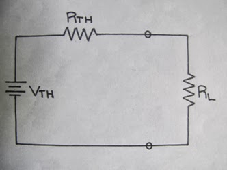
Thevenin’s Equivalent
Circuit
Another theorem used in circuit analysis is the Norton’s
Theorem. This theorem is related to Thevenin’s Theorem by source
transformation. We also replaced fixed circuit into an equivalent circuit. This
circuit is consists by a short circuit current (Isc) or Norton’s current (In)
connected in parallel with a resistor (Rn) which is the equivalent resistance
when all independent sources were turned off. Rn is equal to Rth (Rn=Rth).
Using this equality, we can solve for Norton’s current by dividing Rth from Vth
(Vth/Rth).

Norton’s Equivalent Circuit
In various practical situations, we design a circuit to
provide power to the load. There were also situations that we need to maximize the power deliver to the load and Thevenin’s Theorem will greatly contribute with
this. This maximum power will only occur when load resistance is equal to the
Thevenin’s resistance (RL=Rth). This is the theorem of maximum power.
The
power delivered will vary to the load resistance. It only means that if the
load resistance changes, power also changes. We can also calculate maximum
power using this formula:
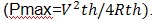

Maximum Power
This
Chapter taught me how to analyze a specific circuit by just transforming or
simplifying the circuit and replacing it into an equivalent circuit. In actual
applications, I've learned that these ways of transformations and theorems can
be used in trouble shooting. Like in our household, every time a variable load
is changed, we have to analyze the circuit again and again. Through Thevenin’s
Theorem, we can trouble shoot it to avoid this kind of problem.
CAPACITORS
AND INDUCTORS:


Capacitor Symbol

Inductor Symbol
Sample
Experience:
During
the construction of our power supply, I placed a light emitting diode (LED) in
series with a resistor to test if our power supply functions. Then I suddenly
observe after I plugged out the transformer, the LED doesn't turned off
automatically. A question generated in my mind that, “What is the reason behind
why it happened”? Then I found out during our circuit class about capacitor and
inductor that it is because of the presence of the capacitor in our circuit due
to the stored energy on it. The transformer in our power supply serves as an
inductor since it is consists of coil of conducting wires.
In
this Chapter, I've learned the great significance of capacitor and inductor in
an electric circuit. It answered some of my questions of what really their
purpose why they are placed in a specific circuit. Both of them are useful for
they serves as temporary voltage and current sources because of their capacity
to store energy. They are also frequency sensitive that’s why they are useful
for frequency discrimination. Capacitors oppose any change in voltage while
inductors oppose any change in current.
FIRST
ORDER CIRCUIT:
-Source
Free RC Circuit
-Source
Free RL Circuit
In
analyzing RC and RL circuits, we apply Kirchhoff’s Laws like in resistive
circuits. Through using these laws, we arrived in an algebraic equation but, if
we use RC and RL laws, we arrived in a differential equation. One way of
exciting a circuit is through source free circuit. When DC source is suddenly
disconnected, the source free RC circuit occurs. The energy stored in the
capacitor is released. Using this approach, always be in mind that the capacitor
acts as an open circuit to steady state DC conditions. In analyzing source free
RL circuit, the inductor acts as a short circuit to steady state DC conditions.
In RC
analysis, we first find the initial voltage across a capacitor while in RL circuits, we first solve for the initial current through the inductor. It is
also important to calculate for the time constant of
the circuit in both RC and RL analysis. The smaller the time constant, the
faster the rate of decay of response due to the quick dissipation of energy
stored. The larger the time, the slower the rate of decay of response because
it takes longer time to reach the steady state. But whatever the time constant is, the circuit will reach its steady state
after five time constant.

Source Free RC Circuit Source
Free RL Circuit
As we observed in our household appliances such as television, rice cooker and other electric device with power lights, when we turn on these appliances, the power light will automatically turned on. It is due to fast charging time. But when we plugged out these appliances, the power light will slowly turned off due to slow discharging time and slow rate of decay.
charrr hahah xD..
TumugonBurahin