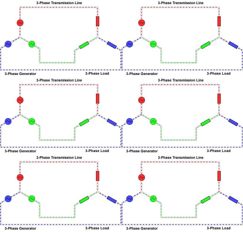
THREE-PHASE
CIRCUITS
CONTENTS:
-Introduction
-Balanced
Three-Phase Voltages
-Definition
of terms
-Balanced
Wye-Wye Connection
-
Balanced Wye-Delta Connection
-
Balanced Delta-Delta Connection
-
Balanced Delta-Wye Connection
-Examples
and Applications
-Practice
Sample Problems
-Learnings
INTRODUCTION:
From
our past lessons, we always dealt with single-phase circuits. A
single-phase ac power system is consists of a generator connected to
a pair of wires to a load. These pair of wires is what we called
transmission line. Polyphase are circuits or systems which the ac
sources operate at the same frequency but different phases. A
two-phase system is produced by a generator consisting of two coils
placed perpendicular to each other so that thee voltage generated by
one lags the other by 900
while a three-phase system is produced by a generator consisting of
three sources having the same amplitude and frequency but out of
phase with each other by 1200.
See
the difference of the said three systems above by means of figures:

Single-phase
two wire system
Two-phase
three wire system

Three-phase
four wire system
In
our household, we single-phase three wire system because the terminal
voltages have the same magnitude and the same phase. Also, whether it
is single-phase, two-phase or three-phase system, we can’t put load
as many as we can. We must also consider the power supplied by the
source if it is enough to accommodate certain number of loads.
Example of this is a power amplifier we’ve made; we have 70V and 8A
a total of 560W power. Our power amplifier is 100W so; I can say that
there must only 10 100-W power amplifier that must be put in the
circuit.
BALANCED
THREE-PHASE VOLTAGES
Three-phase
voltage is often produced by a three-phase ac generator. Balanced
phase voltages are equal in magnitude but different in phase angle
because they are out of phase with each other by 1200.
A three-phase system is equivalent o three single-phase circuits. A
voltage sources can be connected either wye-connected or
delta-connected. Loads can also be connected either wye or delta
connectio 
DELTA CONNECTION
WYE CONNECTION
There
are also two types of phase sequence, one is positive or abc sequence
in which Van
leads
Vbn
which
in turn leads Vcn.
The other one is negative or acb sequence in which Van
leads
Vcn
which
in turn leads Vbn.
This
phase sequence is the time order in which the voltages pass through
their respective maximum values.

NEGATIVE SEQUENCE
NOTE:
A
balanced load is one in which the phase impedances are equal in
magnitude and in phase. Wye connected load has impedances connected
in neutral node while delta connected has impedances connected around
a loop.
DEFINITION
OF IMPORTANT TERMS:
Line
current - current flowing from the generator to the load in each
transmission
line
line
voltage - the voltage between in each pair of lines
phase
current – current flowing through each phase
phase
voltage – voltage of each phase
BALANCED
WYE-WYE CONNECTION
A
balanced Wye-Wye system is a three-phase system with a balanced
connected source and a balance connected load. We can solve for its
line current by getting a single-phase loop from the circuit and
applying KVL.
BALANCED
WYE-DELTA CONNECTION
A
balance wye-delta system consists of a balanced wye-connected source
and a balanced delta-connected load. This connection is perhaps the
most practical three-phase system. We can also solve for its phase
currents by getting a loop from the circuit then apply KVL. Line
currents are obtained from the phase currents that were solved by
applying KCL at node A,B, and C.
For
alternative or another way of analyzing and solving wye-delya
connection, we may transform the delta –connected load to
wye-connected load by using delta-wye formula:
BALANCED
DELTA-DELTA CONNECTION
A
balanced delta-delta system is one in which both the balanced source
and balanced load are delta-connected. For easy analyzing the
delta-delta connected circuit, transform both the source and the load
to their wye equivalent.
SUMMARY:
BALANCED
DELTA-WYE CONNECTION
A
balanced delta-wye system consists of a balanced delta-connected
source and a balanced wye-connected load. There are also the line
voltages as well as the phase voltages. We can generate an equation
through getting a loop from the circuit and this may help us solved
for the line currents. Like in other connections, we may also
transform delta-connected source to wye-connected source.
SAMPLE
PRACTICE PROBLEM:
Answers:
12< -600
A,
12<
-1800
A, 20< 600
A,
20.78<
-900
A, 20.78< 1500
A, 20.78< 300
A
LEARNINGS:
After
the partial discussion of three-phase system, I’ve learned that in
a wye-connected balanced source, line currents and phase currents are
equal while in a delta-connected balanced source, line voltage and
phase voltage is equal. For solving, its easy to solve the required
parameters if the system is a wye-wye connection because it has a
single-phase equivalent circuit that is easy to analyze. Also, I’ve
found out that the electric power is generated and distributed in
three-phase at the standard operating frequency.


